INTERNATIONAL: Target Image Analysis using White’s Spectra V3i SCAN feature
As I claimed a couple weeks ago, I’ve decided to begin publishing my personal study about the possibility to have a basic TARGET IMAGE ANALYSIS using the White’s Spectra V3i. Obviously I couldn’t demand a true professional imaging analysis like the one gained by sampling raw datas directly from the detector electronics as on some scientific publication, especially focusing humanitarian demining. (see EUDEM et alii materials)
Methodological Foreword
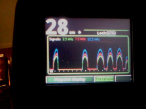
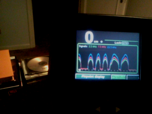
Spectra V3i users probably are already aware that one of the most interesting graphical screen is the so called SCAN GRAPH or simply SCAN. This tracing graphic could be enabled in the Live Search, in the PinPoint Mode or in the Analysis Screen mode too. This special representation graphic allows to visualize the signal intensity of the selected operating frequency (mono or multi frequency) and its time variation. The graphic trace will scroll with a (programmable) speed allowing the user to see how the signal’s intensity change during the sweeps.
Each frequency has its own colour:
A) 2.5 kHz – GREEN
B) 7.5 kHz – RED
C) 22.5 kHz – BLUE
Since I’ve begun to test this special graphic mode, I immediately have thought that maybe it could be interesting to study how different traces can be obtained by sweeping on different targets.
I’ve collected some target samples and I’ve begun my work. I’ve thought to do a somehow analytical examination by just managing some simple air test at first. I’ll do other test on buried targets on a later moment to highlight differences, variation and common issues.
My work will be published in (at least) two parts, beginning with some basic tests and then going on the field. Obviously I don’t expect identical results but I think it will be absolutely interesting to see if and how the graphic behaviour will change in different situations.
In this first article, as I’ve already said, I will describe the tracings with some selected target. I’ve passed these target about 10 cm (5 inches) from the V3i’s stock coil (D2, 10″ Double D coil). I’ve loaded the factory preset HI-PRO and I’ve made no modifications apart from activating the SCAN tracing in the PinPoint Screen. I wanted not to modify the settings in order to have a very stable machine and to allow other people’s testing the easy way.
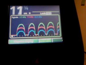
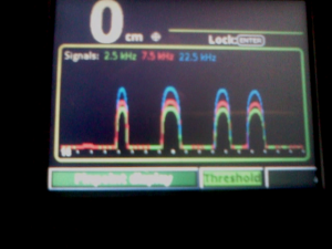
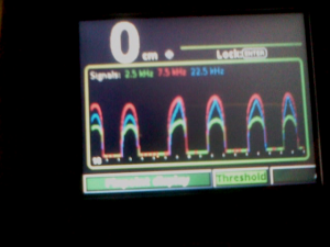
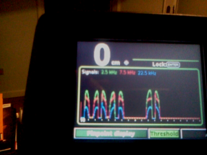
Some targets were passed horizontally (WEST-EAST orientation) and vertically (NORTH-SOUTH orientation) to highlight some peculiar differences. Sweep speed was EXTREMELY low. This to obtain the best variation resolution that, with faster sweeps, wouldn’t be so good. I’ve also shot a video of the experiment that I’ll put online in the next days. I’ve taken some screenshots from this video that I’ve analysed and commented. I want to beg you pardon for the pics’ bad quality but due to some technical problems, I have had to use my smartphone camera that doesn’t bright for crispness. They are, however, enough good for the scope. Together with the pics, I’ve put some notes regarding:
1) Target type
2) Special orientation
3) Sweep direction, when not on the WEST-EAST line
4) The frequency dominancy order: 1st, 2nd and 3rd
5) A descriptive note
Once again, it has to be clear that this is an experimental work and it doesn’t pretend to reveal any “miracle” information. My project’s aim is about knowing more about the Spectra V3i’s Image Analysis capabilities in order to use them on the field with a sufficient reliability factor.
Let’s start with the sample targets list:
1) 1 Euro Cent
2) 5 Euro Cent
3) 20 Euro Cent
4) 50 Euro Cent
5) 1 Euro
6) 2 Euro
7) 200 Lire (* related graphs are not included in this article)
8) 10 Cent of King Vittorio Emanuele (1857)
9) 2 Baiocchi e Mezzo (XVII century)
10) Small white gold ring (approx. 1 gram)
11) Small yellow gold chain (approx. 3 grams)
12) Iron nail
13) Yellow Gold Wedding Ring (3 grams)
14) Very thin yellow g0ld medal (less than 1 gram)
15) Modern pulltab
16) Small piece of tin foil
17) Old, rusty and pierced crown Bottlecap
18) Old crown Bottlecap in average conditions
19) Brand new crown Bottlecap
Dominant Frequencies Analysis
Before taking a look to the images and reading the related comments, the first analysis to do is about the dominant frequencies for every target. In the following table I’ll collect the “Arrival Order”: 1st, 2nd and 3rd frequency by its amplitude on the SCAN graph. During the experiments I’ve noticed one important issue. At least on the air tests, no substantial dominancy changes occur when changing target orientation. This is fundamental to get a reliable and dependable information on the field, where target can have a variety of tri-dimensional position.
| Target |
2.5 kHz |
7.5 kHz |
22.5 kHz |
| 1 Euro Cent |
2 |
1 |
3 |
| 5 Euro Cent |
2 |
1 |
3 |
| 20 Euro Cent |
2 |
1 |
3 |
| 50 Euro Cent |
2 |
1 |
3 |
| 1 Euro |
2 |
1 |
3 |
| 2 Euro |
3 |
1 |
2 |
| 200 Lire |
2 |
1 |
3 |
| 10 Cent King Vittorio Emanuele |
1 |
2 |
3 |
| 2 Baiocchi e Mezzo |
1 |
2 |
3 |
| Small White Gold Ring |
3 |
2 |
1 |
| Small Yellow Gold Chain |
3 |
2 |
1 |
| Iron Nail |
2 |
1 |
3 |
| Yellow Gold Wedding Ring |
3 |
1 |
2 |
| Very thin Yellow Gold Medal |
3 |
2 |
1 |
| Modern Pulltab |
3 |
1 |
2 |
| Small piece of tin foil |
3 |
2 |
1 |
| Old, rusty and pierced crown Bottlecap |
3 |
2 |
1 |
| Old crown Bottlecap in average conditions |
3 |
2 |
1 |
| Brand new crown Bottlecap |
3 |
1 |
2 |
Let’s resume in the following table how many times, for the analysed targets, each frequency was the 1st dominant or in 2nd or 3rd position.
| Frequency |
1° |
2° |
3° |
|
2.5 kHz |
2 |
7 |
10 |
|
7.5 kHz |
11 |
8 |
0 |
|
22.5 kHz |
6 |
4 |
9 |
Examining this first simplistic and incomplete analysis (it lacks of silver, steel, lead, bronze or other important alloy targets) we can infer that, on the observed sample of targets, the most efficient frequency seems to be the 7.5 kHz that appear to be the 1st dominant 11 times on 19 targets, 2nd dominant 8 times and never on the 3rd place. 22.5 kHz will follow with 6 times 1st and 2.5 kHz closes with only 2 times first dominant on 19 samples.
IMAGE ANALYSIS
a) Euro Coins

 While analysing targets from the Euro Coin family, from 1 cent to 2 Euro coinage, the winning frequency is, without any doubt, the 7.5 kHz that appears to be 1st dominant on every tested Euro coin. To be noticed is the bizarre behaviour on the 1 EuroCents and 5 EuroCents coins. In both occasions, when the coin is just under the middle of the Spectra’s coil, 7.5 and 2.5 kHz will suddenly collapse while the 22.5 kHz literally jumps in 1st position. Just as the coin get past the middle of the coils, 22.5 kHz will fall and immediately the other 2 frequencies will raise. In my personal opinion we should take consider the coins’ metal composition and the “Skin Effect” to correctly interpret this strange behaviour. Both 1 EuroCent and 5 EuroCent (see also 2 EuroCent that’s not in the sample list) have a iron core and are covered by a very very thin copper plating. The “Skin Effect”, in a very simplistic way, is a physics phenomenon that forces electric currents to stay on the conductor surface when the applied frequency rises. The higher the frequency, the more superficial will be the current flux. In this case I’m talking about the electromagnetically induced current on the targets generated by the metal detector. We already know that low frequencies have a stronger penetration on ground and big targets while high frequencies have a better sensitivity on small and thin targets thanks to the Skin Effect.
In my opinion, talking about the 1 and 5 eurocents, the Spectra, at first, has a dominancy of the lower frequencies that have a better target penetration and allow the machine to “see” the iron internals. When the electromagnetic field reaches its intensity maximum (near the middle of the coil), the machine starts to see the superficial copper plating thanks to the 22.5 kHz allowing the correlated graph to jump in first position while other collapse.

 Another thing to be noticed is about the 2 Euro coin where traces are not as “round” as with other coins and tend to become somehow “conic” or “spikey”. In my opinion, the bi-metallic composition has a fundamental influence on the graph shape. We have to keep in mind that, on the 2 Euro coin, the external crown has a greater percentage of nickel (it’s made of a nickel and copper alloy) content compared to the internal disc making it less conductive. This should possibly explain the “conic” shape especially confronting it with the 1 Euro coin that has the greatest conductivity on the external crown due to the higher copper concentration (less nickel) and take advantage of that to generate a greater eddy current thanks to its ring shape.
b) Old coins

 When analysing the older coins (King Vittorio Emanuele’s 10 cents and 2 Baiocchi e Mezzo) with their generous dimensions and their copper composition, we see that 2.5 kHz is the winning frequency, validating the physics rule that tell us that lower frequencies has a better sensitivity on highly conductive targets. To be noticed the “flat” graphs of 7.5 and 22.5 kHz on the 10 Cent and the proportional equidistance (33%, 66%, 99%) of the 3 frequencies on the 2 Baiocchi e Mezzo.
c) Gold items and small piece of tinfoil


 Here’s a targets group that will surely raise the interest of many hunters: a small white gold ring, a yellow gold wedding ring, a very thin yellow gold medal, a thin yellow gold chain and… a small piece of tinfoil. Due to the small size of 4 of 5 items (the wedding ring is 3 grams so, actually, is not very tiny) we should have been expected a 22.5 kHz dominancy that, in fact, was confirmed. With the 3 grams wedding ring we had a better result (this was expected too) with the 7.5 kHz thanks to its superior surface and higher conductivity. Keeping the wedding ring apart, the arrival order of the frequency on the other gold items and the piece of tinfoil is always equal: 1st 22.5 kHz, 2nd 7.5 kHz and 3rd 2.5 kHz. We also have to remember that these targets’ VDI (a more complex analysis on VDI will be published in the second part of my work), are very close to each other and usually fall between 0 and 15 (Note: Wedding ring has usually a higher values around 30-35) when the V3i is going multifrequency. By taking a first look at the graphs, it may seem that Image Analysis is not able to help us to choose to-dig-or-not-to-dig with these targets. Obviously the first thing we would like to screen is the tinfoil from the gold items. Will we be forced to dig to solve the mistery? Maybe not…At least sometimes…
If the piece of tin foil is relatively small or, otherwise, if it has a very irregular shape, probably the graphs trend will be different from the ones shown in this articole. They may display a very narrow peak (tiny tinfoil) or some quick peaks and collapses (irregular shaped tinfoil). Due to the great interest on this kind of targets, I will focus on specific studies in the next future to try to produce some (I hope) reliable information that will be useful for the treasure hunters.
d) Modern (Squared) Pulltab
Analysing the pulltab was very interesting. Even if they are usually made of aluminum, the dominant frequency is the 7.5 kHz. Probably is due to the regular shape and the two holes that make they appear like a sort of “8” that let conductivity to be enough for the 7.5 kHz. A very curious issue is tied to the peculiar 22.5 and 2.5 kHz graphic shape. While the dominant 7.5 is relatively round, 22.5 (2nd best) has a neat “spikey” shape and 2.5 has light “spikey” shape. To be remarked that these sort of triangular shapes come up even if the pulltab’s position is on the WEST-EAST axys or in the NORTH-SOUTH one. This Image Analysis could be very important if it will be validated, even partially, with the field tests.
e) Iron nail with squared head and section
I’ve also examined a nice old and rusty iron nail, with a squared head and section. I’ve taken some time to analyse this kind of targets due to its common presence on my fields.
This kind of target produced the most curious Imaging results connected with the spatial positioning. When it is on the NORTH-SOUTH orientation, one thing that caught my attention is the 2.5 and 22.5 almost complete coupling.
If we put the nail on the WEST-EAST position, we will notice a sort of double peak with a peculiar “lung shape” graph with a sudden collapse of the 3 frequencies when passing under the middle fo the coil.
Last test was on the nail while kept on its vertical. Here it happens something really weird. The dominant frequency, 2.5 kHz, gets conical while the second one (7.5) goes flat and the third one (22.5) has a round shape.
f) Crown bottlecaps
The last targets group was the one of crown bottlecaps. I’ve choosen several types, from the more rusty (it was pierced too) to the brand new one. I’ve tested them with their crown downward and upward to verify different behaviours. A very weird thing that caught my attention was the dominant frequency: always 22.5 kHz! It has to be said that, in most cases, the three frequencies’ intensities are very close to each other and sometimes they completely overlap. The ordinary graph shape is “conic” and sometimes tend to go flat when the bottlecap is on its edge. A very peculiar behaviour is the one of the brand new bottlecap with the “conic” 7.5, a “flat” 2.5 and a “collapsing” 22.5 when the target passes the middle of the coil.
First conclusions

By ending this first preliminary tests, made by passing target in front of the coil, I could state to have had an experience of a solid evidence of an informative content of these graphs. Sometimes I could dare to say I had seen a sort of target’s “fingerprint”, thanks to the bold characterization of the tracings. It will sound obvious to you that the most interesting, and definitive, test will be with buried targets.
Honestly I don’t expect the same results! I think I’ll see variations, sometimes in a dramatic way, biased by depth and soil’s conditions. As I’ve said in my foreword, this work doesn’t want to give “miracle” results. My wish it is that it could become a small brick for further and deeper insights and studies that, in a not so far future, could lead to better low cost image analysis systems embedded in our beloved metal detectors.
Leonardo/”Bodhi3”
Director AMDTT












Continuate così, bravi!
Grazie mille Marco! Sei gentilissimo!
Leonardo
Direttore AMDTT